I have found that while I do for the most part enjoy the build process, I have also really enjoyed meeting, speaking with and corresponding with air racing enthusiasts, full size and RC builders, and historians associated with the Laird Super Solution, as well as lots of people who just love antique aircraft.
For me this has been a great side benefit, and makes it much easier while building in Dubai.
There is almost no interest in Antique or sport aviation in this region, so It is a real pleasure when I can speak with like minded individuals.
I am also amazed at the amount of really talented artists and illustrators who have chosen the Super Solution as a subject.
The other day I was surprised to be contacted by Jim Newman. Jim is the artist who drew the Laird Super Solution Cutaway drawing for the EAA museum many years ago.
I have this drawing front and center in my little shop, and refer to it constantly, it has been a huge asset, and I am very thankful Jim made the effort at the time they were building the EAA replica to produce this fantastic drawing.
There is even a picture in the EAA Super Solution book, (now long out of print) of Jim with clipboard in hand recording the details of the Super Solution.
It is a real pleasure to be in contact with Jim, who is a former RAF pilot, and is still active in aviation.
Jim tells me he currently has a number of these posters available, so if anyone is keen I can provide Jim`s contact details on request.
I was also recently sent some CAD drawings by an RC modeller from Slovakia who is in the process of recreating the Super Solution digitally, and is extremely detail oriented. The drawings to date are amazing, and highly detailed as well. I am really looking forward to seeing the model he builds from these.
It is great to see the interest level still high for this wonderful aircraft, and lets hope there are many more RC models built and flown.
I have also corresponded with, the artist of this beautiful drawing, Lyle Brown. I love the way he has captured the aircraft, it looks like it is basking on the ramp, ready to leap forward!
If anyone is interested in a copy of this beautiful drawing, it can be ordered via:
http://fineartamerica.com/featured/laird-super-solution-lyle-brown.html
The build process of a racing Biplane from the Golden Age of Air Racing (And other racing replica projects)
Sunday, 25 March 2012
finally something other than wings!
The original (and the EAA replica) had steel airfoil shaped ribs, and an all welded constuction.
I would guess that they hydroformed the originals? and the EAA ribs were made over bucks.
As I do not currently have a 1000 ton press in my garage, I decided to go the alternate route and use a big hammer.I began by having a set of 1/2 inch thick steel rib templates water jet cut.
But when they came back from the water jet cutter they were pretty crude, and while the basic profile was there, they needed alot of clean up, and the edges radiused.
This was my first experience with water jet cutting, so I am not sure if this was a fair example of the process, but I would be hesitant to use it again over laser cutting.
I had to make two form blocks for each rib profile to allow the 025 4130 material to be sandwiched in between.
I then made up a set of templates to cut the 4130 sheet blanks out.
Next I cut the blanks out, bolted them into their respective pairs of steel form blocks and proceeded to whack the ribs into shape. After having recently made so many aluminum ribs and formers for the ailerons, I forgot how much harder you have to hit steel. The ribs proved to be a good workout.
The various vertical and horizontal fin ribs are now formed, still to complete are the flanged lightening holes, but these are on hold as I have ordered a set of combination punch, and flanging dies, and they are enroute via dogsled or similar based on how long they are taking!
I have left the ribs slightly long to allow for an exact fit on assembly.
Once the holes are all punched an flared, I can build some basic assembly boards, bend the various 4130 tubes and start to fit the ribs.
I now have a set of very heavy steel rib form blocks, stored away gathering dust along with every other one off fixture no longer needed.
Maybe I should put up a photo of my fixture graveyard, although I find it rather painful to look at, so maybe not.
wing fitting attach locating assemblies
I decided that I needed to build fixtures to mount the wing attach fittings to the fuselage.
As my basic welded fuselage is currently being fabricated in Toowoomba, Australia, this presented some issues with matching wings to fuselage.
(a small distance issue)....
The best way I could think of to accomplish this was to build dummy wing sections of the upper and lower wings, and mount the actual fittings in place. This then ensures that the wings will bolt to the fuselage exactly. (fingers crossed)
I built the lower wing fixture to be stub sections of both the Left hand and Right hand wings. The tube in the leading edge was for alignment only, but the tube behind the rear spar locates the aileron spar, and diameter to ensure there will be no longeron to aileron interference issues. I removed the fittings from the LH and RH wing spars and used them on the fixture, so all should line up on assembly.
Should being the operative word.
The top wing only required a spar assembly which locates the center attach fitting, and the rib profiles each side to set the incidence.
I plan that a side benefit of these two jigs will be to use them to fabricate the wing to fuselage fairings, as it is much easier to fit fairings on a stub wing assembly than to have the actual wings in place.
I boxed up these two jigs and shipped them off to Australia, where they are now on hand for fitting fitment.
As my basic welded fuselage is currently being fabricated in Toowoomba, Australia, this presented some issues with matching wings to fuselage.
(a small distance issue)....
The best way I could think of to accomplish this was to build dummy wing sections of the upper and lower wings, and mount the actual fittings in place. This then ensures that the wings will bolt to the fuselage exactly. (fingers crossed)
I built the lower wing fixture to be stub sections of both the Left hand and Right hand wings. The tube in the leading edge was for alignment only, but the tube behind the rear spar locates the aileron spar, and diameter to ensure there will be no longeron to aileron interference issues. I removed the fittings from the LH and RH wing spars and used them on the fixture, so all should line up on assembly.
Should being the operative word.
The top wing only required a spar assembly which locates the center attach fitting, and the rib profiles each side to set the incidence.
I plan that a side benefit of these two jigs will be to use them to fabricate the wing to fuselage fairings, as it is much easier to fit fairings on a stub wing assembly than to have the actual wings in place.
I boxed up these two jigs and shipped them off to Australia, where they are now on hand for fitting fitment.
Ailerons
I have now managed to complete the assembly of the second aileron, and I am quite happy to see them assembled and moving nicely.
I am happy that they have turned out almost friction free, and move easily, but this also makes me concerned about flutter. I am quite amazed at how much weight is required fwd of the hinge points, somwhere around 4 pounds per aileron! but this can not be determined exactly until I rivet the ailerons together, and this will have to wait until the inspection.
So with the fittings now all attached, and the wires in place, the only part left to do on the lowers is the leading edge and tip plywood, which again shall be after the inspection.
When I stand back and look at these two wings with ailerons I am just amazed at how much time they have sucked up!, I think I could have finished a single seat Pitts in the same time these have taken. But they are done, and the balance of the top wing is much easier to complete.... I hope.
I am happy that they have turned out almost friction free, and move easily, but this also makes me concerned about flutter. I am quite amazed at how much weight is required fwd of the hinge points, somwhere around 4 pounds per aileron! but this can not be determined exactly until I rivet the ailerons together, and this will have to wait until the inspection.
So with the fittings now all attached, and the wires in place, the only part left to do on the lowers is the leading edge and tip plywood, which again shall be after the inspection.
When I stand back and look at these two wings with ailerons I am just amazed at how much time they have sucked up!, I think I could have finished a single seat Pitts in the same time these have taken. But they are done, and the balance of the top wing is much easier to complete.... I hope.
Saturday, 18 February 2012
Top wing progress
With the ailerons worked out I thought it was time to start the steel parts for the top wing.
More jigs!
I really envy guys building RV`s, their parts come in a box, mine are somewhere in steel sheets.
Anyway, the top wing has a central attach fitting, built up of plates and tubing, with bent up U channel fittings holding it all together.
I made up matching sets of steel plates, and match drilled them. I then bent up some steel u channel fittings.
They had to be bent to match the lower taper on the front and rear spars.
I then made an assembly and welding fixture. This has an aluminum channel base, 2 stub spars, and a channel to hold the fore to aft tube.
I wanted this fixture to be very solid, as the plates and the tube are quite thick and so require lots of heat when welding.
Once all the parts were made, and securely bolted in the fixture they were welded.
Regards the actual welding, all finish TIG welding is done by my good friend Christiano.
Chris is an extremely talented welder, and machinist, who moonlights as a Boeing 777 Captain.
Once the assembly popped out of the jig I put it on the wing, and amazingly it fit.
With this central fitting now complete I can work outwards in both directions, making the wire tabs and I strut attach fittings.
Once the tabs are all done, I can measure and order for the top wing drag anti drag wires, and get them underway.
I will also work out the wing tip lights, which I am looking forward to.
I shall try not to burn the wing down in the process.
More jigs!
I really envy guys building RV`s, their parts come in a box, mine are somewhere in steel sheets.
Anyway, the top wing has a central attach fitting, built up of plates and tubing, with bent up U channel fittings holding it all together.
I made up matching sets of steel plates, and match drilled them. I then bent up some steel u channel fittings.
They had to be bent to match the lower taper on the front and rear spars.
I then made an assembly and welding fixture. This has an aluminum channel base, 2 stub spars, and a channel to hold the fore to aft tube.
I wanted this fixture to be very solid, as the plates and the tube are quite thick and so require lots of heat when welding.
Once all the parts were made, and securely bolted in the fixture they were welded.
Regards the actual welding, all finish TIG welding is done by my good friend Christiano.
Chris is an extremely talented welder, and machinist, who moonlights as a Boeing 777 Captain.
Once the assembly popped out of the jig I put it on the wing, and amazingly it fit.
With this central fitting now complete I can work outwards in both directions, making the wire tabs and I strut attach fittings.
Once the tabs are all done, I can measure and order for the top wing drag anti drag wires, and get them underway.
I will also work out the wing tip lights, which I am looking forward to.
I shall try not to burn the wing down in the process.
EFIS 1931 style
It is interesting to see exacting replicas, or restored antiques, which have modern instruments installed in them.
I know of one fellow who is currently planning on fitting a full glass cockpit to a 1930`s Monocoupe. Ouch!
Well I have been trying to locate all of the original instruments, and have so far managed to find most of them.
The original SS had a mix of Pioneer and US gauge instruments fit, some were quite unique, others fairly generic.
Probably the most unique was the Pioneer Turn and Bank with the "shiny steel ball"
This was only made for a very short time, as I believe the ball would become magnetised and the compass would always point at the T&B.
(Not an ideal result in an airplane designed for cross country racing)
I managed to locate this exact T&B
Another fairly hard to find instrument is the Pioneer Bubble face compass. They do come up time to time, but they are getting very expensive. I was lucky to locate this one some time ago.
I have also found the floor mounted second compass which was installed for the trans continental record flights.
I will be interesting to see if they both agree after rebuild, I guess this aircraft needs 2 correction cards.
I have had mixed results to date with the balance of the instruments, I have most of the engine instruments, with the exception of the correct RPM gauge.
I have also found a few suitable Lunkheimer primers, and the correct Scintilla mag switch.
Regards the flight instruments, again I have some, but not all.
I have the correct pioneer ROC, but I have yet to locate the correct Altimeter and ASI.
I would really like to hear from anyone who may have the correct ASI, ALT, or Tach and would like to sell or trade them. I do have plenty of other instruments for trade.
Here is a list of all the instruments as originally fit:
Pioneer floor compass and drift meter
Pioneer Airspeed 50 to 350 mph 175 at bottom dead center
Pioneer turn and bank 3 1/8th No dog houses shiny steel ball
Pioneer rate of climb +/- 2000 fpm 1000' at bottom, 2000' at 3 O'clock
Pioneer tachometer 600-3000 rpm. 1900 rpm at Bottom dead center
Altimeter, insensitive 0 to 15000' setting know at bottom dead center
cylinder head temp 0 to 600 F
US gauge oil temperature 2 1/4 0 to 100 C 50 degrees at top dead center
US gauge oil pressure 2 1/4 0 to 120 psi 60 psi at top dead center
US gauge fuel pressure 2 1/4 0 to 10 psi 5 psi at top dead center
mag switch scintilla vintage
Once I have all the correct instruments I will send them off in one shipment for rebuild.
Based on the available visibility I may as well fit a DVD player in the panel, at least you could watch an inflight movie!
I know of one fellow who is currently planning on fitting a full glass cockpit to a 1930`s Monocoupe. Ouch!
Well I have been trying to locate all of the original instruments, and have so far managed to find most of them.
The original SS had a mix of Pioneer and US gauge instruments fit, some were quite unique, others fairly generic.
Probably the most unique was the Pioneer Turn and Bank with the "shiny steel ball"
This was only made for a very short time, as I believe the ball would become magnetised and the compass would always point at the T&B.
(Not an ideal result in an airplane designed for cross country racing)
I managed to locate this exact T&B
Another fairly hard to find instrument is the Pioneer Bubble face compass. They do come up time to time, but they are getting very expensive. I was lucky to locate this one some time ago.
I have also found the floor mounted second compass which was installed for the trans continental record flights.
I will be interesting to see if they both agree after rebuild, I guess this aircraft needs 2 correction cards.
I have had mixed results to date with the balance of the instruments, I have most of the engine instruments, with the exception of the correct RPM gauge.
I have also found a few suitable Lunkheimer primers, and the correct Scintilla mag switch.
Regards the flight instruments, again I have some, but not all.
I have the correct pioneer ROC, but I have yet to locate the correct Altimeter and ASI.
I would really like to hear from anyone who may have the correct ASI, ALT, or Tach and would like to sell or trade them. I do have plenty of other instruments for trade.
Here is a list of all the instruments as originally fit:
Pioneer floor compass and drift meter
Pioneer Airspeed 50 to 350 mph 175 at bottom dead center
Pioneer turn and bank 3 1/8th No dog houses shiny steel ball
Pioneer rate of climb +/- 2000 fpm 1000' at bottom, 2000' at 3 O'clock
Pioneer tachometer 600-3000 rpm. 1900 rpm at Bottom dead center
Altimeter, insensitive 0 to 15000' setting know at bottom dead center
cylinder head temp 0 to 600 F
US gauge oil temperature 2 1/4 0 to 100 C 50 degrees at top dead center
US gauge oil pressure 2 1/4 0 to 120 psi 60 psi at top dead center
US gauge fuel pressure 2 1/4 0 to 10 psi 5 psi at top dead center
mag switch scintilla vintage
Once I have all the correct instruments I will send them off in one shipment for rebuild.
Based on the available visibility I may as well fit a DVD player in the panel, at least you could watch an inflight movie!
Functional Art
The propeller has now been returned, inspected, assembled, certified and is ready to mount.
It looks beautiful, but was the original polished? probably not, but I shall take a mulligan on this one, it just looks too good to paint!
I persuaded my wife that the propeller was much safer sitting in our front room on a stand, as opposed to tucked away in a crate.
So I built a stand.
We get plenty of comments, most are favorable.
The propeller is 9 feet long, with a 5406 30-spline hub and W2 blades.
The propeller has been quite a saga; I managed to find a few 5406 30-spline hubs some time ago. I then located and bought a set of 4350 blades, as I thought they were going to be suitable. It turned out they were not suitable for the horsepower, but I was fortunate to then find a set of correct blades, and trade my 4350 blades for them.
I then sent all the blades, the hub and parts to The Prop Shop, in Oklahoma, who did a really nice job assembling and certifying all the components. The blade angle has initially been set to 12.5 degrees, which is probably a good first setting.
We were also able to locate a set of the correct 1931 Hamilton Standard decals, which have been applied to the blades, and finish them off nicely.
This assembly is probably as close to the original propeller as can be assembled today. I still have a 2D30 Constant speed propeller which we could use if required, but as it would have a large adverse CG effect, I would not want to use it if possible, although it would be a better prop to explore the envelope.
(but what a great excuse to build another airplane)
I found an interesting comment in a write up by Gen Doolittle on testing the Super Solution, he mentioned they set the blade angle over 30 degrees! And it took over 8000 feet to get off the ground the first flight!
This brings up a couple of points, one they must have had a BIG field, and two, why would you keep going after the first 3-4000 feet?
Anyway, once it got on the step he said it went pretty fast.
Time flies!
Well, it would appear it has been a while since I last posted.
This is not, as some have suggested :) due to a lack of progress, but I have been in that stage of building where a huge amount of work produces almost nothing to look at.
My main progress of late has been the ailerons. It turned out that building the ailerons is almost as big a job as building the wings.
The original aircraft ailerons had a steel tube spar, (similar to the Ryan STA method) with aluminum nose ribs, aluminum main ribs, aluminum rear spar, and trailing edge.
The hinges are permanently attached to the tube, and held in place by steel brackets.
First step in building the ailerons was to work out the actual size and articulation. Since I know the airfoil and chord, as well the hinge points are fixed, I could work out the size of the aileron. I have no idea what the original travel was, but based it on basic practice, max 25 degrees up and down, with no bias as of now.
The white material shown is teflon. I was able to get a large section of 1/ 1/4 inch thick teflon block. This stuff drills and machines really well, and holds up well to the forming process. I understand it is extremely expensive, but luckily I did not have to find out!
Once all the aluminum rib sections had been formed, I started on the steel brackets which would mount to the 4130 steel tube spar. I decided the best way to mount the brackets accurately would be via a tube section which slid over the spar, and I would rosette weld the tubes with the bracket attached, as this would minimise heating the ailerons spar, (I was concerned about distortion over the 8 foot length, as it has 3 hinge attach points.
To make the brackets, I cut the tube sections, and also the steel plates. I cut multiple steel plates from .040 4130 sheet by making a cutting block I could run an air nibbler around.
Once the tubes and plates had all been made, for a total of 48 brackets (more on why so many later) I made up a fixture to weld them in LH and RH pairs.
Once all the LH and right hand brackets had been welded, and cleaned up, I could start assembling the ailerons.
I then needed to permanently locate the hinge locations to the rear spar, and I had been concerned about drilling holes directly through the wooden blocks which glue behind each hinge point.
I decided to try and mount the hinges via a "floating bushing" arrangement, which would hopefully self align the attach bolts.
I made up bushings which fit within the hinge, and over the attach bolts. I then milled a square cut through the wooden blocks which was about 1/16th wider and deeper than the bushing.
I cut grooves into the bushing (065 wall) for better glue adhesion, (but realised later where could the bushing possibly go anyway!!)
The theory is that by glueing the block over the bushing and allowing the glue to set with the spar and hinges bolted in position, there will be no misalignment of the three hinge positions. The difficult part is not permanently glueing the aileron to the wing in the process.
But thankfully once the glue dried the bolts slid out (pre waxed) and the hinges released nicely.
The spar now moved freely on the wing, with no friction or binding. I polished the spar tube under each hinge location, but it`s a shame the original did not allow for some sort of bearing, rather than tube on tube.
Next step was to rosette weld the LH and RH attach brackets in place on the spar, which locates the leading edge aluminum brackets, and also locate the rear ribs on an aluminum U channel which I bent up from 032 2024 T3 aluminum.
I cut down some standard trailing edge stock to more closely match the original width.
I ran the trailing edge through a shrinker to shape the section which matches to the wing tip bow.
I made up a separate steel attach bracket, as well as smaller nose and main tip ribs, to match the tip bow area. The aileron tapers in this area both in width and depth. More router jigs, form blocks, drill blocks.
I then fit the 5/8th aluminum tube through the ribs and drilled it to secure.
The next step was to form and mount the leading edge sections. I started by rolling some sections of 020 2024 T3 sheet to get the basic shape, the built a fixture to mount them to the leading edge brackets.
By moving the uprights to different locations I was able to drill and mount each section.
Once all the leading edge sections had been drilled, I removed them and trimmed each to the final size, and refit the aileron to the wing for a final check.
To complete the ailerons to pre cover stage the following needs to be done:
Paint the steel aileron spar black.
Form the curved section of 5/8th aluminum tube at the tip.
Replace all clecos with screws, bolts, and rivets as required.
Add a counterweight in the leading edge section.
*I suspect the original did not have counter balanced ailerons, and with so much weight behind the hinge point why did it not flutter at speed? well the EAA replica may show why. When I moved the aileron on the EAA version it was almost solid, now I imagine that 20 years sitting in a museum does not help, but I noticed the ailerons were mounted directly via bolts through the spar, and this obviously created a great deal of binding friction. If the original was done the same way, then it would have been very hard to move the ailerons, and this may have actually helped to counter act flutter.
Then again, Gen Doolittle had so many other issues associated with flying and racing the SS, maybe he forgot to mention it also had the odd indication of flutter!
My ailerons are almost friction free at this point, so I think it would be critical to balance them at minimum 10% nose down, (110% total weight forward of the hinge point)
I have temporarily hung a steel weight to give an idea of balance, but without all the correct fasteners in place and the clecos removed, as well the fabric and paint estimated, I cannot determine the required weight yet.
Due to the extremely short area ahead of the hinge, it will take a substantial weight to balance them.
I have allowed attach points between the steel leading edge brackets to attach a balance weight tube, and this will be completely hidden.
I will also need to leave the leading edges un rivetted at this stage to allow for the Canadian stage inspection.
The RH aileron is also all ready to assemble, with all parts completed, so this should go together quite quickly compared to the first one!
This is not, as some have suggested :) due to a lack of progress, but I have been in that stage of building where a huge amount of work produces almost nothing to look at.
My main progress of late has been the ailerons. It turned out that building the ailerons is almost as big a job as building the wings.
The original aircraft ailerons had a steel tube spar, (similar to the Ryan STA method) with aluminum nose ribs, aluminum main ribs, aluminum rear spar, and trailing edge.
The hinges are permanently attached to the tube, and held in place by steel brackets.
First step in building the ailerons was to work out the actual size and articulation. Since I know the airfoil and chord, as well the hinge points are fixed, I could work out the size of the aileron. I have no idea what the original travel was, but based it on basic practice, max 25 degrees up and down, with no bias as of now.
I started by making the aluminum rear ribs. These take a number of fixtures, one to router the blanks, another to router the lightening hole, another to drill the loactor holes, another to bend the LH and RH flanges, and another to bend the attach flange.
Once I had the rear ribs done, I started on the small leading edge attach ribs. They are also aluminum, and attach to the steel brackets which are welded to the spar. The process for these was the same as the rear ribs, router and forming fixtures. I determined that I would need 12 nose ribs per aileron, 7 LH and 5 RH, so it involved alot of cutting, drilling and forming.The white material shown is teflon. I was able to get a large section of 1/ 1/4 inch thick teflon block. This stuff drills and machines really well, and holds up well to the forming process. I understand it is extremely expensive, but luckily I did not have to find out!
Once all the aluminum rib sections had been formed, I started on the steel brackets which would mount to the 4130 steel tube spar. I decided the best way to mount the brackets accurately would be via a tube section which slid over the spar, and I would rosette weld the tubes with the bracket attached, as this would minimise heating the ailerons spar, (I was concerned about distortion over the 8 foot length, as it has 3 hinge attach points.
To make the brackets, I cut the tube sections, and also the steel plates. I cut multiple steel plates from .040 4130 sheet by making a cutting block I could run an air nibbler around.
Once the tubes and plates had all been made, for a total of 48 brackets (more on why so many later) I made up a fixture to weld them in LH and RH pairs.
Once all the LH and right hand brackets had been welded, and cleaned up, I could start assembling the ailerons.
I then needed to permanently locate the hinge locations to the rear spar, and I had been concerned about drilling holes directly through the wooden blocks which glue behind each hinge point.
I decided to try and mount the hinges via a "floating bushing" arrangement, which would hopefully self align the attach bolts.
I made up bushings which fit within the hinge, and over the attach bolts. I then milled a square cut through the wooden blocks which was about 1/16th wider and deeper than the bushing.
I cut grooves into the bushing (065 wall) for better glue adhesion, (but realised later where could the bushing possibly go anyway!!)
The theory is that by glueing the block over the bushing and allowing the glue to set with the spar and hinges bolted in position, there will be no misalignment of the three hinge positions. The difficult part is not permanently glueing the aileron to the wing in the process.
But thankfully once the glue dried the bolts slid out (pre waxed) and the hinges released nicely.
The spar now moved freely on the wing, with no friction or binding. I polished the spar tube under each hinge location, but it`s a shame the original did not allow for some sort of bearing, rather than tube on tube.
Next step was to rosette weld the LH and RH attach brackets in place on the spar, which locates the leading edge aluminum brackets, and also locate the rear ribs on an aluminum U channel which I bent up from 032 2024 T3 aluminum.
I cut down some standard trailing edge stock to more closely match the original width.
I ran the trailing edge through a shrinker to shape the section which matches to the wing tip bow.
I made up a separate steel attach bracket, as well as smaller nose and main tip ribs, to match the tip bow area. The aileron tapers in this area both in width and depth. More router jigs, form blocks, drill blocks.
I then fit the 5/8th aluminum tube through the ribs and drilled it to secure.
The next step was to form and mount the leading edge sections. I started by rolling some sections of 020 2024 T3 sheet to get the basic shape, the built a fixture to mount them to the leading edge brackets.
By moving the uprights to different locations I was able to drill and mount each section.
Once all the leading edge sections had been drilled, I removed them and trimmed each to the final size, and refit the aileron to the wing for a final check.
To complete the ailerons to pre cover stage the following needs to be done:
Paint the steel aileron spar black.
Form the curved section of 5/8th aluminum tube at the tip.
Replace all clecos with screws, bolts, and rivets as required.
Add a counterweight in the leading edge section.
*I suspect the original did not have counter balanced ailerons, and with so much weight behind the hinge point why did it not flutter at speed? well the EAA replica may show why. When I moved the aileron on the EAA version it was almost solid, now I imagine that 20 years sitting in a museum does not help, but I noticed the ailerons were mounted directly via bolts through the spar, and this obviously created a great deal of binding friction. If the original was done the same way, then it would have been very hard to move the ailerons, and this may have actually helped to counter act flutter.
Then again, Gen Doolittle had so many other issues associated with flying and racing the SS, maybe he forgot to mention it also had the odd indication of flutter!
My ailerons are almost friction free at this point, so I think it would be critical to balance them at minimum 10% nose down, (110% total weight forward of the hinge point)
I have temporarily hung a steel weight to give an idea of balance, but without all the correct fasteners in place and the clecos removed, as well the fabric and paint estimated, I cannot determine the required weight yet.
Due to the extremely short area ahead of the hinge, it will take a substantial weight to balance them.
I have allowed attach points between the steel leading edge brackets to attach a balance weight tube, and this will be completely hidden.
I will also need to leave the leading edges un rivetted at this stage to allow for the Canadian stage inspection.
The RH aileron is also all ready to assemble, with all parts completed, so this should go together quite quickly compared to the first one!
Tuesday, 30 August 2011
21 foot wing, 18 foot garage.
I knew the wing would not fit easily in my garage, basic math told me that, but now that it is in 3 dimension form, it becomes alarmingly clear just how much room it takes up.
I continued to build the the top wing ribs through early July, and also started to work on the spar center splice joints. I had not been looking forward to these splice joints, as for an 1 1/2 thick spar, at a 15-1 ratio splice, the joint would be 22 inches long. This is a large splice.
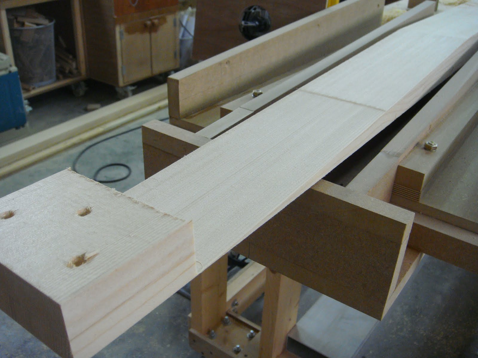
So I built a router jig to cut the splices in each board.
I got the idea for this jig and the method of cutting from Dave Binkley, who is building a beautiful 1932 Monocoupe 110, the restoration of which is nicely decribed on his site;
http://gobinkley.com/
Dave does beautiful work, and it was really handy to see how he had worked out this splice method.
(thanks again Dave)
I spent a day building up the router jig, and testing it with a short length of spar.
The main points to note,
The spar has to be held completely secure, if there is any movement, it will affect the taper joint, and this is especially true as it gets to the end, which decreases to a feather edge.
It is very important to limit each pass cut depth to less than a 1/16th of an inch, any more and the router will be working too hard,and could move the spar or dig in.
Make sure via a solid base, the router cannot tip.
Go slow, methodically, and do not cut with the gyroscopic rotation. (huh?)
this means that as the router bit turns, do not try to cut into the rotation, this will let the bit wander and run away, you should always be pulling the router against the rotation. This is probably easier to do than explain, but it is pretty important.
I left the spar 3 inches long in at the end of the jig, to allow me to screw it down, then as each pass is made the jig cuts deeper into the end, and eventually, after about 30-40 passes, you have a 22 inch perfect taper.
I have a 1/2 inch shaft Makita router, which is a pretty heavy duty unit, I would not want to try this splice with a 1/4 inch shaft router, as I am not sure it would be rigid enough, I guess it would work, but it would probably require a great many more passes, as the cut depth would be so slight, as well a 1/2 inch straight bit only requires 50% as many passes to cover the same width and length.
So after a few rather nerve wracking hours, I had completed the 4 required splices to create two main spars.
and as usual, my capable assistant, displaying the appropriate safety equipment, was with me every step of the way.
Once the splices were complete, next step is to glue them, not an overly complex step, but I did make sure that when I made up the joint, first I spread normal mixed T88 on both surfaces, let this soak in for about 10 minutes, and then mixed micro balloons into the remaining epoxy and re spread over the joint surfaces, I did this to ensure that the glue would stay in the joint and not migrate out under pressure.
(note the seemingly never ending process of rib construction in the background)
Once both spars had been joined at the center, I marked out all rib locations, and also cut the various plywood doublers which are at fitting attach points.
When I was building the ribs, I had to keep adjusting my rib fixtures to allow for the various thickness plywood which the ribs must fit over, and in some cases different thickness at the front and rear spar points, this all takes time, but it worked out well, and each rib fit nicely over the planned plywood plates.
Now that all ribs are done, all 72 of them, I can honestly say I have had enough of building ribs!! I worked out I have about 800 hours into the ribs alone, this covers the parts cutting, and preparation, the various jigs and assembly fixtures, and all of the assembly. I think I could have built an RV6 start to finish in about the same time as the ribs have taken.
Here is a simple little tool I made to check the spar centers as I went along. The Super Solution spars sit at 20 inches from front to back, at the center, so to accurately measure this, I lathe turned two short sections of 3/16th stainless rod to a point at one end, and threaded the other ends with a 1032 die.
I drilled a section of aluminum angle at exactly 20 inch centers, and it becomes a handy center checking tool. This replaces the expensive trammel sets which can be used here as well, but this costs next to nothing.
By using a longer aluminum section and routing a channel at one end, this can be used as an adjustable trammel set to true the drag / anti drag wire bays.
I had to halt production for a family holiday in Thailand, we left mid July, and spend 3 weeks in Hua Hin, south of Bangkok, a beautiful beach resort.
The holiday was fantastic! but I was back home in Dubai early August for work, and production resumed. My family stayed in Thailand an additional 3 weeks, so I had the house, and more importantly, the garage to myself, which made for some very productive days.
I wanted to complete all of the wing woodwork, which meant I had to laminate the two tip bows, build the three tapered ribs, and also the leading edge boards.
After the lower wing tip bow disasters, I got smart, and asked David Oviatt to please send "full size" templates of the tip bow, and the three tapered end ribs. He had already worked all of this out in CAD, so he was able to produce and send these drawings.
What an incredible difference, no guessing, I was able to take the full size drawings, build a table for the tip bow (the wing was now taking up the entire bench) and in short order build two perfect tip bows, both identical, and the corrrect shape, the first time!
It is amazing to see how effective CAD can be, when an expert such as David uses it.
also by modifying my existing full size rib jigs, I was able to build the smaller versions of the truss and compression ribs.
With all of the structural woodwork now complete, I decided to take the wings outside for a group photo, the first time they have left the garage, and been outside.
The next step will now be to make all of the metal fittings for the top wings, and there are alot! over 50 separate parts, so much cutting, drilling and welding to go. I am a little more realistic after the lower wings, and I expect the metal parts will take me about a month and a half.
I will be able to now accurately measure the drag / anti drag wires, as there is such little room for error, and order them from Russ, at Vintage Aero in New Zealand. They will take a couple months to produce.
Then it is a a matter of assembling all together, at this point none of the ribs are glued in the top wing, as the spars still need drilling once the fittings are made.
However, I can now see the end in sight for the wings, and I am already looking forward to switching gears onto the fuselage, the tubing for which has been patiently hanging on the wall for a year now.
I continued to build the the top wing ribs through early July, and also started to work on the spar center splice joints. I had not been looking forward to these splice joints, as for an 1 1/2 thick spar, at a 15-1 ratio splice, the joint would be 22 inches long. This is a large splice.
So I built a router jig to cut the splices in each board.
I got the idea for this jig and the method of cutting from Dave Binkley, who is building a beautiful 1932 Monocoupe 110, the restoration of which is nicely decribed on his site;
http://gobinkley.com/
Dave does beautiful work, and it was really handy to see how he had worked out this splice method.
(thanks again Dave)
I spent a day building up the router jig, and testing it with a short length of spar.
The main points to note,
The spar has to be held completely secure, if there is any movement, it will affect the taper joint, and this is especially true as it gets to the end, which decreases to a feather edge.
It is very important to limit each pass cut depth to less than a 1/16th of an inch, any more and the router will be working too hard,and could move the spar or dig in.
Make sure via a solid base, the router cannot tip.
Go slow, methodically, and do not cut with the gyroscopic rotation. (huh?)
this means that as the router bit turns, do not try to cut into the rotation, this will let the bit wander and run away, you should always be pulling the router against the rotation. This is probably easier to do than explain, but it is pretty important.
I left the spar 3 inches long in at the end of the jig, to allow me to screw it down, then as each pass is made the jig cuts deeper into the end, and eventually, after about 30-40 passes, you have a 22 inch perfect taper.
I have a 1/2 inch shaft Makita router, which is a pretty heavy duty unit, I would not want to try this splice with a 1/4 inch shaft router, as I am not sure it would be rigid enough, I guess it would work, but it would probably require a great many more passes, as the cut depth would be so slight, as well a 1/2 inch straight bit only requires 50% as many passes to cover the same width and length.
So after a few rather nerve wracking hours, I had completed the 4 required splices to create two main spars.
and as usual, my capable assistant, displaying the appropriate safety equipment, was with me every step of the way.
Once the splices were complete, next step is to glue them, not an overly complex step, but I did make sure that when I made up the joint, first I spread normal mixed T88 on both surfaces, let this soak in for about 10 minutes, and then mixed micro balloons into the remaining epoxy and re spread over the joint surfaces, I did this to ensure that the glue would stay in the joint and not migrate out under pressure.
(note the seemingly never ending process of rib construction in the background)
Once both spars had been joined at the center, I marked out all rib locations, and also cut the various plywood doublers which are at fitting attach points.
When I was building the ribs, I had to keep adjusting my rib fixtures to allow for the various thickness plywood which the ribs must fit over, and in some cases different thickness at the front and rear spar points, this all takes time, but it worked out well, and each rib fit nicely over the planned plywood plates.
Now that all ribs are done, all 72 of them, I can honestly say I have had enough of building ribs!! I worked out I have about 800 hours into the ribs alone, this covers the parts cutting, and preparation, the various jigs and assembly fixtures, and all of the assembly. I think I could have built an RV6 start to finish in about the same time as the ribs have taken.
Here is a simple little tool I made to check the spar centers as I went along. The Super Solution spars sit at 20 inches from front to back, at the center, so to accurately measure this, I lathe turned two short sections of 3/16th stainless rod to a point at one end, and threaded the other ends with a 1032 die.
I drilled a section of aluminum angle at exactly 20 inch centers, and it becomes a handy center checking tool. This replaces the expensive trammel sets which can be used here as well, but this costs next to nothing.
By using a longer aluminum section and routing a channel at one end, this can be used as an adjustable trammel set to true the drag / anti drag wire bays.
I had to halt production for a family holiday in Thailand, we left mid July, and spend 3 weeks in Hua Hin, south of Bangkok, a beautiful beach resort.
The holiday was fantastic! but I was back home in Dubai early August for work, and production resumed. My family stayed in Thailand an additional 3 weeks, so I had the house, and more importantly, the garage to myself, which made for some very productive days.
I wanted to complete all of the wing woodwork, which meant I had to laminate the two tip bows, build the three tapered ribs, and also the leading edge boards.
After the lower wing tip bow disasters, I got smart, and asked David Oviatt to please send "full size" templates of the tip bow, and the three tapered end ribs. He had already worked all of this out in CAD, so he was able to produce and send these drawings.
What an incredible difference, no guessing, I was able to take the full size drawings, build a table for the tip bow (the wing was now taking up the entire bench) and in short order build two perfect tip bows, both identical, and the corrrect shape, the first time!
It is amazing to see how effective CAD can be, when an expert such as David uses it.
also by modifying my existing full size rib jigs, I was able to build the smaller versions of the truss and compression ribs.
With all of the structural woodwork now complete, I decided to take the wings outside for a group photo, the first time they have left the garage, and been outside.
I will be able to now accurately measure the drag / anti drag wires, as there is such little room for error, and order them from Russ, at Vintage Aero in New Zealand. They will take a couple months to produce.
Then it is a a matter of assembling all together, at this point none of the ribs are glued in the top wing, as the spars still need drilling once the fittings are made.
However, I can now see the end in sight for the wings, and I am already looking forward to switching gears onto the fuselage, the tubing for which has been patiently hanging on the wall for a year now.
Wednesday, 22 June 2011
Starting the Top Wing
With the lower wings pretty much complete,
(they still need the leading edges, but I will leave them off for now) it is time to start the Top wing, as it is a bit behind schedule.
The Top wing is 21 feet long, and the chord is 42" but as it has no ailerons, no taper, and no dihedral, it is a pretty simple structure.
I still need to build the lower wing ailerons, but I am waiting for the aluminum spars to be bent and shipped, they are coming from Canada as I cannot find anyone in Dubai who has an accurate brake over 6 feet long.
As the second lower wing went together so much easier than the first, I will build a complete kit for the top wing first, and pre fit everything. This should make the final assembly very quick. On the lower wings, I worked out all the details on the first wing, and then built a "kit" for the second wing.
I have started by making all the parts for the ribs. There are a total of 40 ribs, 30 Truss ribs, 8 compression and two plywood.
as with the lower wings, the ribs are a quite time consuming to build, each rib has 14 parts, 10 spruce and 4 routed plywood. They require a total of 10 cutting, bending, and assembly fixtures, and are assembled with no nails.
I can build 1 -1 1/2 per day, so thats my July mapped out.
I am also starting to laminate and then scarf the top wing spars. The spars have a 15-1 scarf at the center, so I shall have to build a new scarfing jig for them, more on this later.
My shop (garage) building space has recently been cut in half, as we live in Dubai, UAE, and it gets pretty hot here in the summer, I have a deal with my wife;
Once outside temperatures reach 45 degrees C ( 113 F!) then she can keep her truck in the garage,
well it has reached 45 degrees. and next month it will be 50 (122 F)
Thats why all of my benches and tool cabinets are on wheels.
Unfortunately it does not start to cool down here until Mid September, so I have to watch I do not inadvertently stick a spar through her windshield.
Another issue with the temperatures is I keep the garage at a comforatble 20C with AC, but every time the door opens the temps soar to ambient, and it takes a while to cool down again.
It is quite a "dry" heat, so no real issues with humidity in the summer, but it does get extremely humid in the fall, and I would worry about unprotected wood.
(but by this time I shall have once again banished the truck to the driveway)
Anyway, this will not really impact on production, but it does illustrate one more of the "issues" building in this part of the world.
Even the walk from the house to the garage, about 30 feet, is quite miserable in these temperatures.
Ironically, even on the hottest days here, my primary mode of transport lives outside.
The seat gets pretty hot.
(they still need the leading edges, but I will leave them off for now) it is time to start the Top wing, as it is a bit behind schedule.
The Top wing is 21 feet long, and the chord is 42" but as it has no ailerons, no taper, and no dihedral, it is a pretty simple structure.
I still need to build the lower wing ailerons, but I am waiting for the aluminum spars to be bent and shipped, they are coming from Canada as I cannot find anyone in Dubai who has an accurate brake over 6 feet long.
As the second lower wing went together so much easier than the first, I will build a complete kit for the top wing first, and pre fit everything. This should make the final assembly very quick. On the lower wings, I worked out all the details on the first wing, and then built a "kit" for the second wing.
I have started by making all the parts for the ribs. There are a total of 40 ribs, 30 Truss ribs, 8 compression and two plywood.
as with the lower wings, the ribs are a quite time consuming to build, each rib has 14 parts, 10 spruce and 4 routed plywood. They require a total of 10 cutting, bending, and assembly fixtures, and are assembled with no nails.
I can build 1 -1 1/2 per day, so thats my July mapped out.
I am also starting to laminate and then scarf the top wing spars. The spars have a 15-1 scarf at the center, so I shall have to build a new scarfing jig for them, more on this later.
My shop (garage) building space has recently been cut in half, as we live in Dubai, UAE, and it gets pretty hot here in the summer, I have a deal with my wife;
Once outside temperatures reach 45 degrees C ( 113 F!) then she can keep her truck in the garage,
well it has reached 45 degrees. and next month it will be 50 (122 F)
Thats why all of my benches and tool cabinets are on wheels.
Unfortunately it does not start to cool down here until Mid September, so I have to watch I do not inadvertently stick a spar through her windshield.
Another issue with the temperatures is I keep the garage at a comforatble 20C with AC, but every time the door opens the temps soar to ambient, and it takes a while to cool down again.
It is quite a "dry" heat, so no real issues with humidity in the summer, but it does get extremely humid in the fall, and I would worry about unprotected wood.
(but by this time I shall have once again banished the truck to the driveway)
Anyway, this will not really impact on production, but it does illustrate one more of the "issues" building in this part of the world.
Even the walk from the house to the garage, about 30 feet, is quite miserable in these temperatures.
Ironically, even on the hottest days here, my primary mode of transport lives outside.
The seat gets pretty hot.
Subscribe to:
Posts (Atom)