
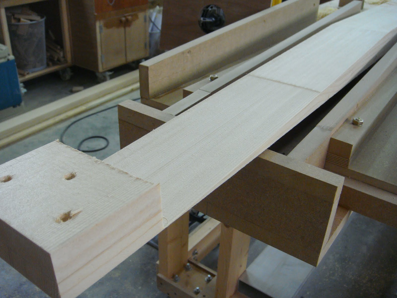
So I built a router jig to cut the splices in each board.
I got the idea for this jig and the method of cutting from Dave Binkley, who is building a beautiful 1932 Monocoupe 110, the restoration of which is nicely decribed on his site;
http://gobinkley.com/
Dave does beautiful work, and it was really handy to see how he had worked out this splice method.
(thanks again Dave)
I spent a day building up the router jig, and testing it with a short length of spar.

The spar has to be held completely secure, if there is any movement, it will affect the taper joint, and this is especially true as it gets to the end, which decreases to a feather edge.
It is very important to limit each pass cut depth to less than a 1/16th of an inch, any more and the router will be working too hard,and could move the spar or dig in.
Make sure via a solid base, the router cannot tip.
Go slow, methodically, and do not cut with the gyroscopic rotation. (huh?)
this means that as the router bit turns, do not try to cut into the rotation, this will let the bit wander and run away, you should always be pulling the router against the rotation. This is probably easier to do than explain, but it is pretty important.

So after a few rather nerve wracking hours, I had completed the 4 required splices to create two main spars.


(note the seemingly never ending process of rib construction in the background)


Now that all ribs are done, all 72 of them, I can honestly say I have had enough of building ribs!! I worked out I have about 800 hours into the ribs alone, this covers the parts cutting, and preparation, the various jigs and assembly fixtures, and all of the assembly. I think I could have built an RV6 start to finish in about the same time as the ribs have taken.

I drilled a section of aluminum angle at exactly 20 inch centers, and it becomes a handy center checking tool. This replaces the expensive trammel sets which can be used here as well, but this costs next to nothing.
By using a longer aluminum section and routing a channel at one end, this can be used as an adjustable trammel set to true the drag / anti drag wire bays.

I had to halt production for a family holiday in Thailand, we left mid July, and spend 3 weeks in Hua Hin, south of Bangkok, a beautiful beach resort.

I wanted to complete all of the wing woodwork, which meant I had to laminate the two tip bows, build the three tapered ribs, and also the leading edge boards.
After the lower wing tip bow disasters, I got smart, and asked David Oviatt to please send "full size" templates of the tip bow, and the three tapered end ribs. He had already worked all of this out in CAD, so he was able to produce and send these drawings.
What an incredible difference, no guessing, I was able to take the full size drawings, build a table for the tip bow (the wing was now taking up the entire bench) and in short order build two perfect tip bows, both identical, and the corrrect shape, the first time!
It is amazing to see how effective CAD can be, when an expert such as David uses it.


I will be able to now accurately measure the drag / anti drag wires, as there is such little room for error, and order them from Russ, at Vintage Aero in New Zealand. They will take a couple months to produce.
Then it is a a matter of assembling all together, at this point none of the ribs are glued in the top wing, as the spars still need drilling once the fittings are made.
However, I can now see the end in sight for the wings, and I am already looking forward to switching gears onto the fuselage, the tubing for which has been patiently hanging on the wall for a year now.